Stair Treads
- General Overview
- Tips and Tricks
- Related Tools
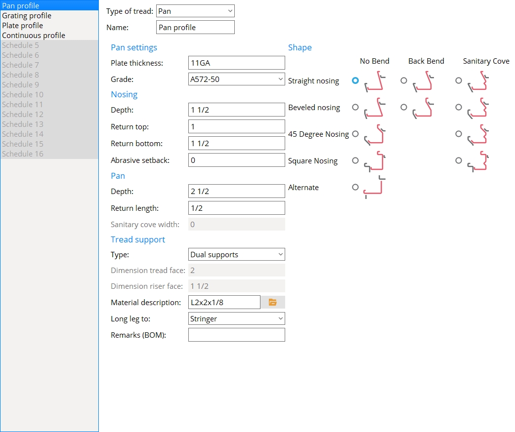
Pan Stair Tread
Type of tread: Pan or Grating or Plate or Continuous.
Pan is currently selected for example.
For Grating see Grating Stair Tread.
For Plate see Plate Stair Tread.
For Continuous see Continuous Stair Tread.
Name: A string of up to 30 characters that is shown on this screen's selection menu and in the list boxes for Intermediate tread schedule, Top tread schedule, and Bottom tread schedule on the Stair Edit window. When you change the name of a stair tread definition, all references to the previously entered name are changed throughout SDS2.
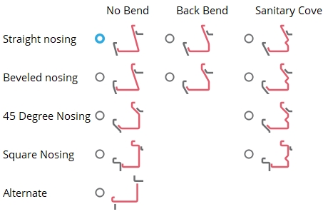
Shape
Select a shape to enable the settings that are relevant to that shape and to disable the settings that are not relevant to that shape.
Pan settings
Plate thickness: The thickness of plate material to be used for the bent plan stair tread.
To enter gage plate: Type in the gage number followed by ga (example: 4ga is rewritten as 4GA when you Tab out of the field). Right-click tells you the stored thickness (based on industry standards), from which the weight of the gage plate is calculated. Allowable gages are any whole number from 3 to 38. You can also enter an exact decimal thickness to get the gage (example: .1345 becomes 10GA when you Tab out of the field). The Description for a gage plate follows the format: bent plate prefix + numberGA + x + width (example: BPL16GAx15 1/2).
Grade: A36 or A572 or etc.. The grade of steel for the bent plate layout material that is used to model the pan treads.
Setup: If the grade of steel you want is not shown on the list box (
), you can use Home > Project Settings > Job > Material Grades > Plate Grades to add it to the list.
Report Writer: MemberMaterial.Material.SubMaterial.MaterialGradeDescription
Advanced Selection: MaterialGrade
Parametric module: MaterialGrade
Nosing
Depth: The vertical distance from the top edge of the nosing to the back bend.
Return top: The horizontal distance from the top nosing bend to the nearest vertical edge. In other words, this is the length of the top edge of the nosing.
Return bottom: The horizontal distance from the top nosing bend to the main bend or the first intermediary bend.
Abrasive setback: The vertical distance that the pan treads are to be offset from the workline of the stair. An Abrasive setback of 0 aligns the nosing line with the workline of the stair. Typically an Abrasive setback is applied in order to model the space that is needed to accommodate abrasive nosing material.
Pan
Depth: The vertical distance from the top of the pan to the top of the adjacent nosing return.
For a pan with a sanitary cove, this is the vertical distance from the top of the pan to the inside (middle) bend of the sanitary cove.
The Pan depth and Sanitary cove width together position the sanitary cove.
Return length: The distance from the pan return bend to the top edge of the pan return.
Sanitary cove width: The horizontal distance from the sanitary cove's inside bend to its upper bend. You may enter a value of 0 (zero) if you do not want a sanitary cove.
Tread support
Type: None or Single support or Dual supports or Bent plate. For a choice other than None, be sure to enter an appropriate Material description.
|
None instructs the stair program to not generate support material for the bent pan treads.
Single support results in a single support (angle, plate, bar) at both ends of each tread. The Material description sets whether the support is an angle, plate, or bar and also specifies the thickness and width of the support. The position and length of the support is calculated automatically based on the tread geometry, and can be reviewed and adjusted under Tread support settings on a Stair Edit window where this stair tread definition is selected.
Dual supports results in two angles, plates, or bars at both ends of the pan: one to support the pan and the other to support the riser. The Material description sets whether the supports are angles, plates, or bars and also specifies the thickness and width of the supports. The position and length of the support is calculated automatically based on the tread geometry, and can be reviewed and adjusted under Tread support settings on a Stair Edit window where this stair tread definition is selected.
Bent plate results in a NS bent plate and FS bent plate as supports for each pan tread. The Material description sets the width and thickness of the bent plate. The Dimension tread face together with the Dimension riser face set the length of the bent plate.
Dimension tread face: The horizontal distance from the inside face of the riser to the end of the bent plate leg that attaches to the tread. This applies when Bent plate is selected as the Type of pan tread support. On the bent plate material in the model, the Dimension tread face is the Length leg 1 of the bent plate.
Dimension riser face: The diagonal distance from the end of the bent plate leg that attaches to the riser to the heel of the tread. This applies when Bent plate is selected as the Type of pan tread support. The Dimension riser face is measured parallel with the riser. On the bent plate material in the model, the Dimension riser face is the Length leg 2 of the bent plate.
Material description: An angle section size or plate description or flat bar description or bent plate description. This applies when Single support or Dual supports has been selected as the Tread support type.
An angle section size may be designated by pressing the file cabinet browse button (
) and double-clicking any section that is on the list of available angle materials that are in the local shape file. Alternatively, you can type in the section size that you want (e.g., L1x1x1/8). Add bolts to tread support on the Stair Edit window gives you the ability to bolt the vertical leg of a tread support angle to the stringer when the tread support Type is Single support.
A plate description is designated by the Plate prefix + thickness x width. For example, PL1/4x1, where PL is the plate prefix.
A flat bar description is designated by the Flat bar prefix + thickness x width. For example, FL1/4x1, where FL is the flat bar prefix.
A bent plate description can be a flat bar description (e.g., FL1/8x1) or a plate description (e.g., PL 1/8x1). Either description results in a bent plate being generated in the model. The Material length and Material thickness of the bent plate is specified in this description.
Long leg to: Stringer or Tread. This applies when an angle with unequal legs has been entered as the Material description. If the legs of the angle are equal, the choice made here does not matter.
Stringer designates at the long leg of the angle is the leg that bolts to the stringer. The leg to stringer is the vertical leg in the installed angle.
Tread designates that the long leg of the angle is the leg that supports the tread. The leg to tread is the horizontal leg in the installed angle.
Remarks (BOM): Any string (up to 23 characters) may be entered. The string of characters might, for example, be the name of the company from which the tread will be purchased, or the tread's part number. The characters entered here populate the Remarks column in the bill of material of any stair that uses this stair tread definition. Updating of the bill of material takes place during Detail Members.
Grating Stair Tread
Type of tread: Pan or Grating or Plate or Continuous.
For Pan, see Bent Pan Stair Tread.
Grating is currently selected for example.
For Plate, see Plate Stair Tread.
For Continuous, see Continuous Stair Tread.
Name: A string of up to 30 characters that is shown on this screen's selection menu and in the list boxes for Intermediate tread schedule, Top tread schedule, and Bottom tread schedule on the Stair Edit window. When you change the name of a stair tread definition, all references to the previously entered name are changed throughout SDS2.
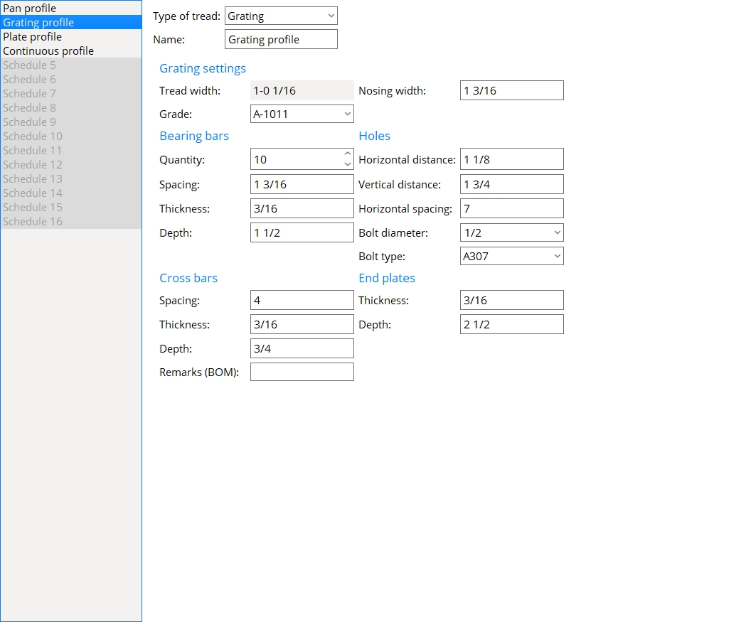
Grating settings
Tread width: read-only. The tread width is calculated from the Nosing width and the Quantity, Spacing, and Thickness of the bearing bars.
Grade: The steel grade that you want applied to the grating treads.
Setup: If the grade of steel you want is not shown on the list box (
Report Writer: MemberMaterial.Material.SubMaterial.MaterialGradeDescription
Advanced Selection: MaterialGrade
Parametric module: MaterialGrade
Nosing width: The width of the nosing plate.

Bearing bars
Quantity: The number of bearing bars.
Spacing: The center-to-center distance between bearing bars.
Thickness: The thickness of the bearing bars.
Depth: The depth of the bearing bars.
Cross bars
Spacing: The center-to-center distance between cross bars.
Thickness: The thickness of the cross bars.
Depth: The height of each cross bar.
Remarks (BOM): Any string (up to 23 characters) may be entered. The string of characters might, for example, be the name of the company from which the stair tread will be purchased, or the tread's part number. The characters entered here populate the Remarks column in the bill of material of any stair that uses this stair tread definition. Updating of the bill of material takes place during Detail Members.
Holes
Horizontal distance: The horizontal distance from the nosing edge of the end plate to the center of the nearest hole.
Vertical distance: The vertical distance from the top edge of the end plate to the center of the hole.
Horizontal spacing: The horizontal distance between the centers of adjacent holes.
Bolt diameter: The diameter of the bolts that are to be inserted into the holes in the end plates.
Welded grating tread: A Bolt diameter of 0 results in grating stair tread without bolts and holes.
To make an entry: You can either type in the diameter of bolt or select it from the list (
Bolt diameter sets hole diameter: Standard round holes are automatically designed in the end plate. The diameter of these holes are calculated from the Bolt diameter per the selected Connection design method.
Bolt type: A307 or A325N or A325SC or A325X or etc. The type of bolt to be used for fastening the tread to the stair stringers.
End plates
Thickness: The thickness of the end plate.
Depth: The height of the end plate.
Plate Stair Tread
Type of tread: Pan or Grating or Plate or Continuous.
For Pan, see Bent Pan Stair Tread.
For Grating, see Grating Stair Tread.
Plate is currently selected for example.
For Continuous, see Continuous Stair Tread.
Name: A string of up to 30 characters that is shown on this screen's selection menu and in the list boxes for Intermediate tread schedule, Top tread schedule, and Bottom tread schedule on the Stair Edit window. When you change the name of a stair tread definition, all references to the previously entered name are changed throughout SDS2.
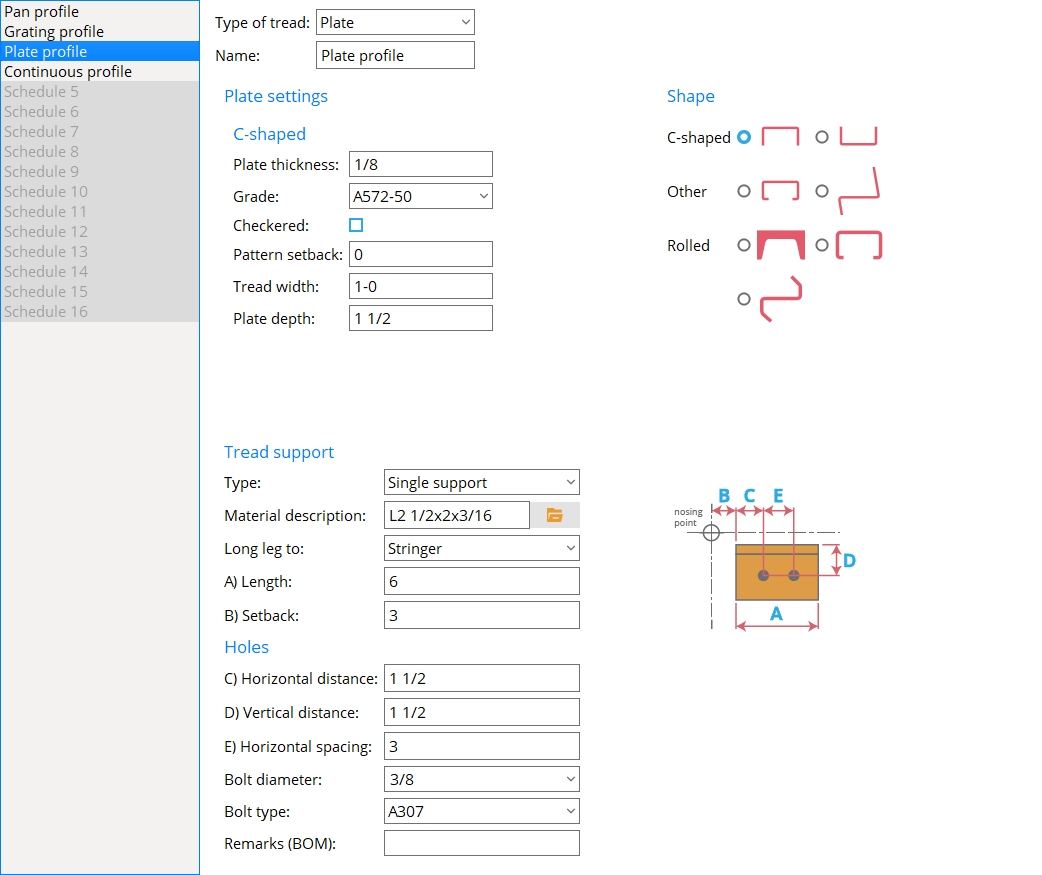
Shape
Select a shape to enable the Plate settings that are specific to that shape.
C-shaped: Down or Up.
Other: Cold formed channel or Other.
Rolled: Rolled channel or Rolled cold formed channel or Rolled cold formed z.
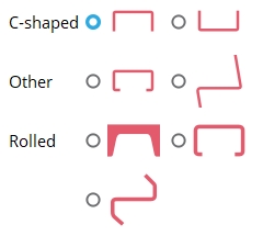
Plate settings
The selected Shape determines which settings are shown here.
C-shaped: Down or Up 
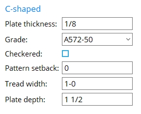
Plate thickness: The Material thickness of the bent plate layout material that is used to model the C-shaped treads.
To enter gage plate: Type in the gage number followed by ga (example: 4ga is rewritten as 4GA when you Tab out of the field). Right-click tells you the stored thickness (based on industry standards), from which the weight of the gage plate is calculated. Allowable gages are any whole number from 3 to 38. You can also enter an exact decimal thickness to get the gage (example: .1345 becomes 10GA when you Tab out of the field). The Description for a gage plate follows the format: bent plate prefix + numberGA + x + width (example: BPL16GAx15 1/2).
Grade: A36 or A572 or etc. The grade of steel for the bent plate layout material that is used to model the C-shaped treads.
Setup: If the grade of steel you want is not shown on the list box (
Report Writer: MemberMaterial.Material.SubMaterial.MaterialGradeDescription
Advanced Selection: MaterialGrade
Parametric module: MaterialGrade
If this box is checked (
), this C-shaped plate tread becomes a checkered plate, which is a steel plate with raised ribs on its top horizontal surface to prevent slippage on the stair treads. The Plate thickness of a checkered plate is measured exclusive of the raised pattern. The prefix set for Checkered in Member and Material Piecemarking is applied to the Description on the General Information window and in the member bill of material (example:Pl3/8x10 becomes CHPL3/8x1) when CH is the prefix and it is set to Append .... It becomes CH3/8x10 when not set to Append...). The Weight of item increases and also may depend on whether Shop bill weight based on material is set to Volume or Dimensions. The plate will be detailed with a checkered pattern.
If the box is not checked (
), the C-shaped plate treads are considered to have smooth near-side surfaces.
Report Writer: XXXXX . CheckeredPlatePattern
Advanced Selection: CheckeredPlatePattern
Parametric module: CheckeredPlatePattern
Pattern setback: The vertical distance that the C-shaped plate treads are to be offset from the workline of the stair. A Pattern setback of 0 aligns the nosing line with the workline of the stair.
|
| In the right example, the Pattern setback is 51 mm (2 inches). |
Tread width: The horizontal distance between the two outside corners of the heel of the C-shaped tread.
Depth: The vertical distance from the heel of the C-shaped stair tread to the toe of either of the two legs. Both legs of a C-shaped tread are this same depth.
Other: Cold formed channel 
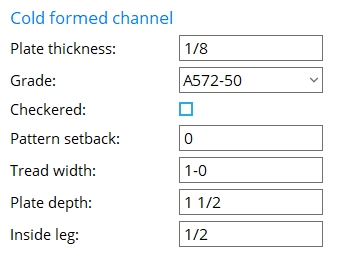
Plate thickness: The Material thickness of the bent plate layout material that is used to model the cold-formed channel treads.
To enter gage plate: Type in the gage number followed by ga (example: 4ga is rewritten as 4GA when you Tab out of the field). Right-click tells you the stored thickness (based on industry standards), from which the weight of the gage plate is calculated. Allowable gages are any whole number from 3 to 38. You can also enter an exact decimal thickness to get the gage (example: .1345 becomes 10GA when you Tab out of the field). The Description for a gage plate follows the format: bent plate prefix + numberGA + x + width (example: BPL16GAx15 1/2).
Grade: A36 or A572 or etc. The grade of steel for the bent plate layout material that is used to model the cold-formed channel treads.
Setup: If the grade of steel you want is not shown on the list box (
Report Writer: MemberMaterial.Material.SubMaterial.MaterialGradeDescription
Advanced Selection: MaterialGrade
Parametric module: MaterialGrade
If this box is checked (
If the box is not checked (
Report Writer: XXXXX . CheckeredPlatePattern
Advanced Selection: CheckeredPlatePattern
Parametric module: CheckeredPlatePattern
Pattern setback: The vertical distance that the cold-formed channel treads are to be offset from the workline of the stair. A Pattern setback of 0 aligns the nosing line with the workline of the stair.
|
| In the right example, the Pattern setback is 51 mm (2 inches). |
Tread width: The horizontal distance between the bends at the top of the cold-formed channel tread.
Depth: The vertical distance from the top of the tread to the bottom of the bent leg of the cold-formed channel tread.
Inside leg: The horizontal distance from the outside vertical face to the toe of the horizontal leg of the cold-formed channel tread.
Other: Other 
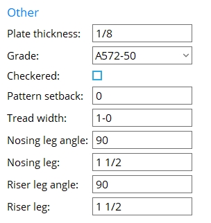
Plate thickness: The Material thickness of the bent plate layout material that is used to model the Other type treads.
To enter gage plate: Type in the gage number followed by ga (example: 4ga is rewritten as 4GA when you Tab out of the field). Right-click tells you the stored thickness (based on industry standards), from which the weight of the gage plate is calculated. Allowable gages are any whole number from 3 to 38. You can also enter an exact decimal thickness to get the gage (example: .1345 becomes 10GA when you Tab out of the field). The Description for a gage plate follows the format: bent plate prefix + numberGA + x + width (example: BPL16GAx15 1/2).
Grade: A36 or A572 or etc. The grade of steel for the bent plate layout material that is used to model the Other type treads.
Setup: If the grade of steel you want is not shown on the list box (
Report Writer: MemberMaterial.Material.SubMaterial.MaterialGradeDescription
Advanced Selection: MaterialGrade
Parametric module: MaterialGrade
If this box is checked (
If the box is not checked (
Report Writer: XXXXX . CheckeredPlatePattern
Advanced Selection: CheckeredPlatePattern
Parametric module: CheckeredPlatePattern
Pattern setback: The vertical distance that the Other type treads are to be offset from the workline of the stair. A Pattern setback of 0 aligns the nosing line with the workline of the stair.
|
| In the right example, the Pattern setback is 51 mm (2 inches). |
Tread width: The horizontal distance from the nosing corner of the tread to the inside face of the riser.
|
Tread width excludes the thickness of the riser leg. |
Nosing leg angle: The degree of angle between the bottom of the tread and the inside face of the nosing leg. This angle must be 90 degrees or less (an acute angle).
|
In this example, the Nosing leg angle is 90 degrees. |
Nosing leg: The distance from the top of the tread to the bottom of the nosing leg.
|
In this example, the Nosing leg length is measured vertically since the nosing leg is vertical. |
Riser leg: The distance from the bottom of the tread to the top of the riser leg.
|
In this example, the Riser leg length is measured vertically since the riser leg is vertical. |
Riser leg angle: The degree of angle between the top of the tread and the inside face of the riser leg. This angle must be 90 degrees or greater (an obtuse angle).
|
In this example, the Riser leg angle is 90 degrees. |
Rolled channel 
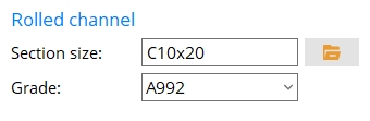
Section size: A section for a channel material (C or MC) that is listed in the local shape file.
|
To generate this example of rolled channel stair treads, a Section size of C10x20 was entered. |
To enter a section size: Either type in the section size that you want, or press the file cabinet browse button
( and double-click a C or MC section that is listed.
Grade: A36 or A572-42 or A588 or etc. The grade of steel for the rolled section material that is used to model the rolled channel treads.
Setup: If the grade of steel you want is not shown on the list box (
Report Writer: MemberMaterial.Material.SubMaterial.MaterialGradeDescription
Advanced Selection: MaterialGrade
Parametric module: MaterialGrade
Rolled cold formed channel 
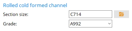
Section size: A section for a cold formed channel material that is listed in the local shape file.
|
To generate this example of rolled cold formed channel stair treads, a Section size of C714 was entered. |
Grade: A992 or A572-42 or A36 or etc. The grade of steel for the rolled cold formed channel treads.
Setup: If the grade of steel you want is not shown on the list box (
Report Writer: MemberMaterial.Material.SubMaterial.MaterialGradeDescription
Advanced Selection: MaterialGrade
Parametric module: MaterialGrade
Rolled cold formed z 
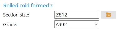
Section size: A section for a cold formed z material that is listed in the local shape file.
|
To generate this example of rolled cold formed z stair treads, a Section size of Z812 was entered. |
Grade: A992 or A572-42 or A36 or etc. The grade of steel for the rolled cold formed z treads.
Setup: If the grade of steel you want is not shown on the list box (
Report Writer: MemberMaterial.Material.SubMaterial.MaterialGradeDescription
Advanced Selection: MaterialGrade
Parametric module: MaterialGrade
Tread support
Type: None or Single support. A tread support can be applied to any tread that can be defined when the Type of tread is Plate.
None gives you stair treads without supports.
Single support places supports (plate, flat bar, or angle) under the stair treads. Settings on this screen such as Material description, Long leg to, and Length control various characteristics of the supports.
Material description: A plate description or flat bar description or angle section size.
A plate description is designated by the Plate prefix + thickness x width. For example, PL1/4x2, where PL is the plate prefix.
A flat bar description is designated by the Flat bar prefix + thickness x width. For example, FL1/4x2, where FL is the flat bar prefix.
An angle section size may be designated by pressing the file cabinet browse button (
Long leg to: Stringer or Tread. This applies when an angle with unequal legs has been entered as the Material description. If the legs of the angle are equal, the choice made here does not matter.
Stringer designates at the long leg of the angle is the leg that bolts to the stringer. This leg will be the vertical leg when the tread and its support are installed.
Tread designates that the long leg of the angle is the leg that supports the tread. This leg will be the horizontal leg when the tread and its support are installed.
Length: The material length of the tread support. The angle, flat bar, or plate support will be cut to this length.
|
In this example, the support is an angle. The tread is a C-shaped plate. |
Setback: The horizontal distance from the nosing point to the support.
|
In this example, the support is an angle. The tread is a C-shaped plate. |
Holes
| Warning: The message Holes are not on support material indicates that a stair in the model that uses this stair tread definition will not have any holes in its tread support angles. To clear this warning so that you get holes and bolts, you may, for example, need to select a different angle (Material description), or you may need to specify a different Vertical distance. |
Horizontal distance: The horizontal distance from the end of the support angle that is nearest the nosing point to the nearest hole in the angle.
|
Holes are placed in the support angle's leg to stringer (the vertical leg). |
Vertical distance: The vertical distance from the top the angle to the nearest hole in the leg to the stringer.
|
A Vertical distance that is too large may result in holes not being on the material. See the warning above. |
Horizontal spacing: The horizontal distance from the center of one hole in the leg to the stringer to the center of the other hole in the leg to the stringer.
|
The Horizontal spacing in this example is the Length of the angle minus twice the Horizontal distance. |
Bolt diameter: The diameter (inches or mm) of the shank of the bolt. This also sets the size of the two standard round holes that will be placed in the angle leg to the stringer (the vertical angle leg).
| diameter |
|
0 results in no holes or bolts. Enter 0 if you want the angles to be welded to the stringers.
3/8 is the default bolt diameter. That diameter will only be shown in the list (
To enter a different bolt size: You can either type in a diameter or select a bolt diameter from the combo box (
Bolt type: A325 or A307 or etc. This is the type of bolt to be used for fastening the vertical leg of the plate tread angle support to the stringer.
Setup: If the bolt type that you want does not appear on the list box (
Remarks (BOM): Any string (up to 23 characters) may be entered. The string of characters might, for example, be the name of the company from which the stair tread will be purchased, or the tread's part number. The characters entered here populate the Remarks column in the bill of material of any stair that uses this stair tread definition. Updating of the stair's bill of material takes place during Detail Members.
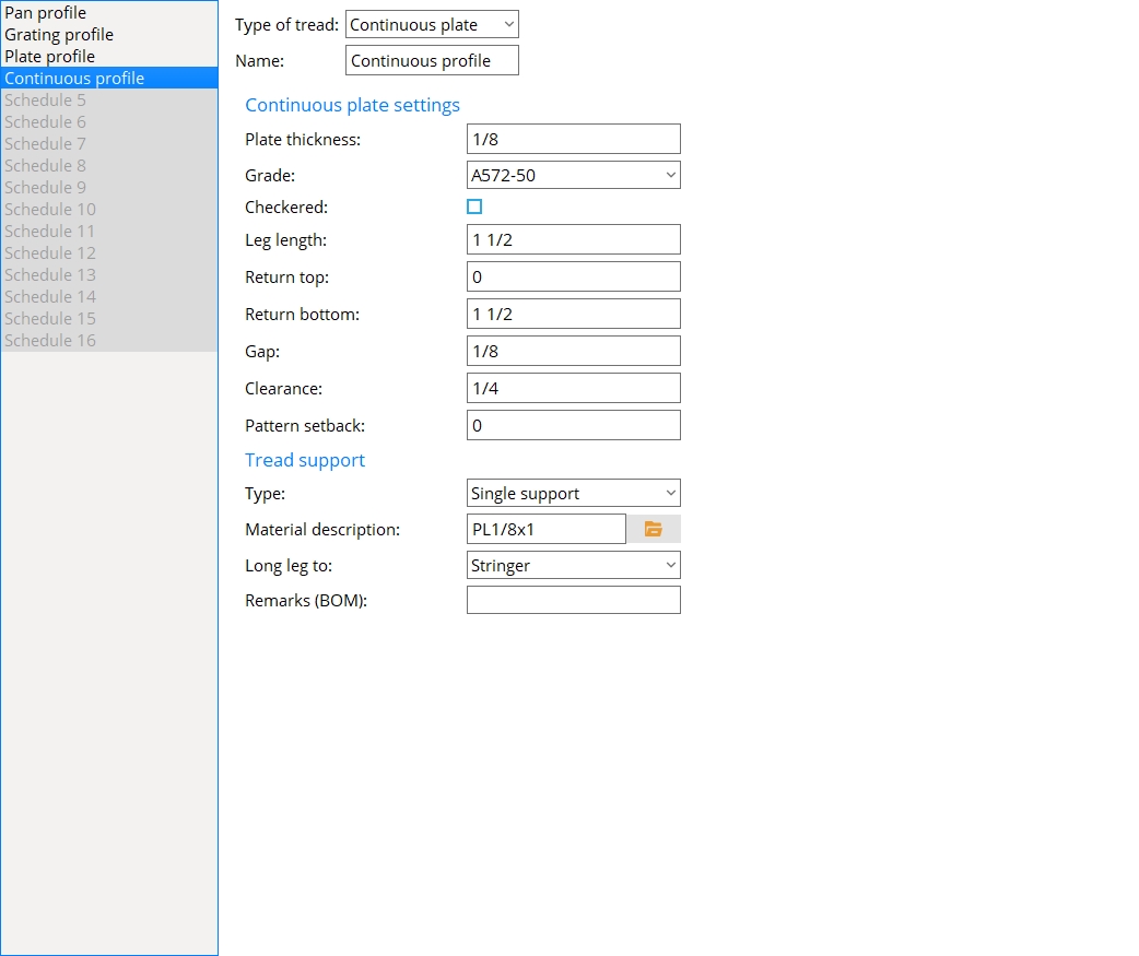
Continuous Stair Tread
Type of tread: Pan or Grating or Plate or Continuous.
For Pan, see Bent Pan Stair Tread.
For Grating, see Grating Stair Tread.
For Plate, see Plate Stair Tread.
Continuous is currently selected for example.
Name: A string of up to 30 characters that is shown on this screen's selection menu and in the list boxes for Intermediate tread schedule, Top tread schedule, and Bottom tread schedule on the Stair Edit window. When you change the name of a stair tread definition, all references to the previously entered name are changed throughout SDS2.
Continuous plate settings
Plate thickness: The Material thickness of the bent plate layout material that is used to model the continuous stair treads.
To enter gage plate: Type in the gage number followed by ga (example: 4ga is rewritten as 4GA when you Tab out of the field). Right-click tells you the stored thickness (based on industry standards), from which the weight of the gage plate is calculated. Allowable gages are any whole number from 3 to 38. You can also enter an exact decimal thickness to get the gage (example: .1345 becomes 10GA when you Tab out of the field). The Description for a gage plate follows the format: bent plate prefix + numberGA + x + width (example: BPL16GAx15 1/2).
Grade: A36 or A572 or etc. The grade of steel for the bent plate layout material that is used to model the continuous stair treads.
Setup: If the grade of steel you want is not shown on the list box (
Report Writer: MemberMaterial.Material.SubMaterial.MaterialGradeDescription
Advanced Selection: MaterialGrade
Parametric module: MaterialGrade
If this box is checked (
If the box is not checked (
Report Writer: XXXXX . CheckeredPlatePattern
Advanced Selection: CheckeredPlatePattern
Parametric module: CheckeredPlatePattern
Leg length: The distance from the corner at the leg bend to the end of the leg.
|
| In this example, the stair's Bottom tread schedule is set to Use Intermediate. Consequently, the bottom tread leg length is the same as the leg length for the intermediate treads. |
Return top: The horizontal distance from the top bend to the end of the top return. If 0 is entered, there will be no top return.
|
| In this example, the stair's Bottom tread schedule and Intermediate tread schedule are both set to use the same tread definition. Consequently, the top return length is the same on each of the treads that are dimensioned. |
Return bottom: The horizontal distance that you want the tread to be extended. A Return bottom of 0 makes the riser perfectly vertical.
|
| In this example, the Return bottom is 51 mm (2 inches). if the Return bottom had been 0, the risers would be perfectly vertical and would align with the construction lines that are shown. |
Gap: The distance from the riser for one tread to the leg for the adjacent tread that is immediately above that tread.
Clearance: The distance from the top of a riser to the bottom of the adjacent tread that is immediately above that riser.
|
The clearance is measured parallel with the riser. |
Pattern setback: The vertical distance that the continuous stair treads are to be offset from the workline of the stair. A Pattern setback of 0 aligns the nosing line with the workline of the stair.
|
| In the right example, the Pattern setback is 51 mm (2 inches). |
Tread support
Type: None or Single support or Dual support.
None results in stair treads without supports.
Single support places a tread support under the tread. The positioning and length of the support is calculated automatically and reported under Tread support settings on a Stair Edit window in which this stair tread definition is specified. Users can adjust the length and positioning of the tread support on that same edit window. Other support dimensions are specified on this screen by entering a Material description.
Dual support puts a tread support under the tread and a riser support on the riser. The positioning and length of these supports are calculated automatically and reported under Tread support settings on a Stair Edit window in which this stair tread definition is specified. Users can adjust the length and positioning of the tread support on that same edit window. Other support dimensions are specified on this screen by entering a Material description.
Material description: A plate description or flat bar description or angle description.
A plate description is designated by the Plate prefix + thickness x width. For example, PL1/4x2, where PL is the plate prefix.
A flat bar description is designated by the Flat bar prefix + thickness x width. For example, FL1/4x2, where FL is the flat bar prefix.
An angle description may be designated by pressing the file cabinet browse button (
Long leg to: Stringer or Tread. This applies when an angle with unequal legs has been entered as the Material description. If the legs of the angle are equal, the choice made here does not matter.
Remarks (BOM): Any string (up to 23 characters) may be entered. The string of characters might, for example, be the name of the company from which the stair tread will be purchased, or the tread's part number. The characters entered here populate the Remarks column in the bill of material of any stair that uses this stair tread definition. Updating the bill of material takes place during Detail Members.
Schedule 5-16
Customize these stair tread definitions as demonstrated by the examples of Pan profile, Grating profile, Plate profile, and Continuous profile.


|
|
OK (or the Enter key) closes this screen and applies the settings.
Cancel (or the Esc key) closes this screen without saving any changes.
Reset undoes all changes made to this screen since you first opened it. The screen remains open.
- Red or yellow exclamation point icons
 or
or 
- Settings applied to the Stair Treads screen are for your current Fabricator. A different set of settings will apply when you Change Fabricator.

